Chassis Design
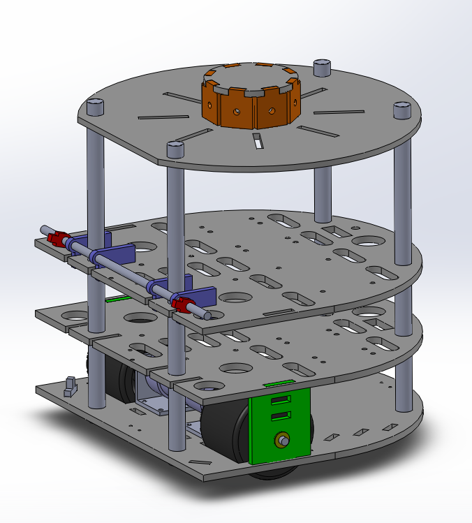
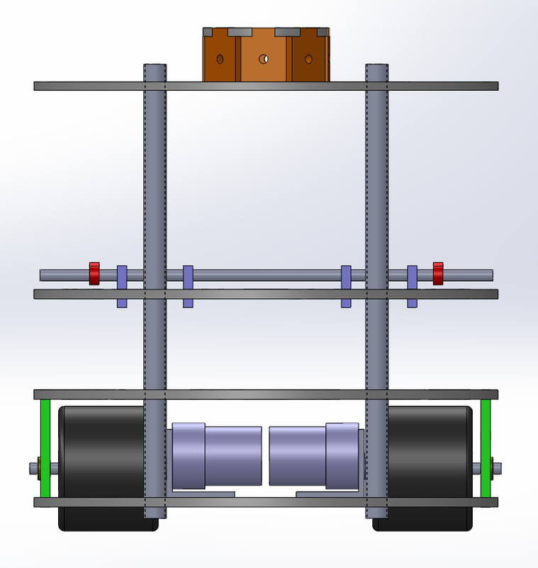
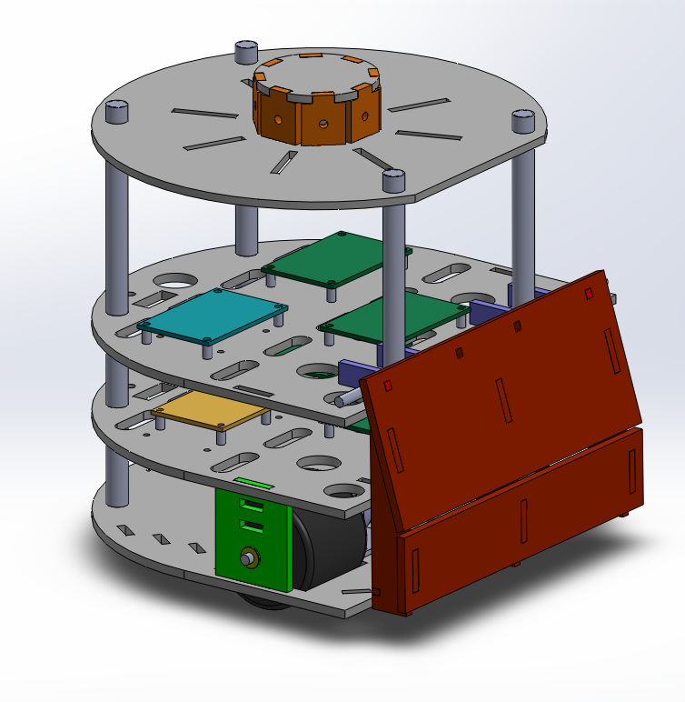
Our chassis design is simple, robust, and modular. It is constructed out of 4 1/4" masonite platforms, which are aligned and supported by 4 1/2" threaded steel rods. The rods made our robot structurally sound, but allowed us to easily move the levels during testing. The bottom level supports the drivetrains, as well as the back caster and motor batteries. The motor supports (green piece above) is sandwiched between the first and second level for added support. The second level contains primarily circuitry - it is home to our H-bridge, tape sensing circuit, and circuitry power board. It also has the battery that supplies power to the electronics. The third level holds the Arduino, bump sensing circuit, and IR beacon sensing circuit. The third level also is where the 4 mounting brackets for the bumper are located, and a steel bar for added weight. The top level is home to the phototransistor array, and is largely barren so as to avoid interference with the IR signals. Each level has a variety of holes so that wires can run between levels.
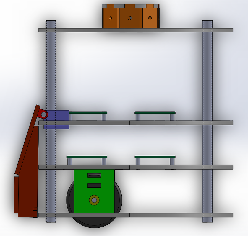
We chose to forward bias our wheels so that we could get more traction near the point of contact with our opponents. We chose a flat front to have a larger more sturdy area to ram bricks and robots alike.
We chose to forward bias our wheels so that we could get more traction near the point of contact with our opponents. We chose a flat front to have a larger more sturdy area to ram bricks and robots alike.
