Tape-Sensing Circuit
Our robot used four OPTEK OPB704WZ IR/LED pairs as tape sensors to detect the edges of the playing field. In order to minimize the number of Arduino pins used to for these tape sensors, the IR transistors were connected between 5 V and a multiplexer (74HC4067), which the Arduino used as a digital switch to swap the tape sensor being sensed.
The tape sensing circuit was designed with a low pass filter in order to eliminate noise from surrounding light sources. A comparator with hysteresis was used to convert this analog signal into a high/low digital signal for the arduino. The LEDs were connected between 5 V and a load resistor of 150 ohms.
The tape sensing circuit was designed with a low pass filter in order to eliminate noise from surrounding light sources. A comparator with hysteresis was used to convert this analog signal into a high/low digital signal for the arduino. The LEDs were connected between 5 V and a load resistor of 150 ohms.
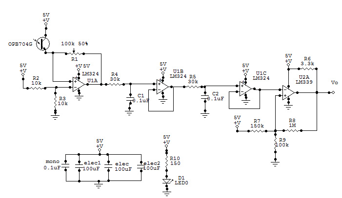
The tape-sensing circuit
