Infrared Beacon Sensing Circuit
Our robot used an array of 8 Lite-On LTR-3208E photo-transistors to detect the various beacons on the playing field. As defined in the project statement, each robot was outfitted with an 850 Hz beacon array, while the sequester was employing the services of a 4 kHz array. While initially we designed two circuits - one to filter each frequency - it became apparent that it was more effective to simply condition the photo-transistor output with hardware and then interpret the frequency in software. In the end, we had a circuit that could reliably detect both beacons at ranges of 10-15 ft.
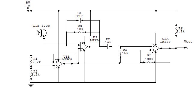
IR Beacon Sensing Circuit
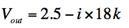
The schematic above shows the beacon sensing circuit. The output of each sensor was fed into an 8 channel multiplexer, and then switched using logic commands from the Arduino (not shown). The output of the multiplexer was then fed into the stage of the circuit. It is important to note that the signal from the phototransistor is not a voltage, but a current that is proportional to the incident light. In order to convert this current into a voltage, a trans-resistive circuit was used. By holding the non-inverting terminal of the LM324 at 2.5V with a buffered virtual ground, we effectively enforced the condition of 2.5V across the phototransistor. The 18K feedback resistor then converts the current into a usable voltage according to the equation:
The capacitor in parallel with the feedback resistor acts as a low pass filter, reducing high frequency noise in the phototransistor signal. The next stage is a high pass filter with cut-off frequency of approximately 100Hz, which attenuates unwanted dc offsets and ambient light while allowing our 850 Hz signal to pass through at about 80% of its former amplitude. The final stage of the circuit is an LM339 comparator in the Schmitt trigger arrangement. It uses a high threshold of 2.53 V and a low threshold of 2.47V. As long as the amplitude of the noise of the signal is less than the magnitude of this hysteresis band, the switch is only triggered once as the signal transitions from high to low. The output of this circuit is a square wave of a frequency corresponding to the beacon source.
